I have had some major issues with this blog since they updated to the new interface. Somehow, my blog got stuck without the ability to change settings, layouts, templates etc. I have not been able to find a solution to the problem. To fix this. I am going to continue my blogging at phoenix.initiate(); It is cleaner, sleeker, easier to read, and I have all of the settings! Don't worry, I transferred all the posts from Man and Machine to phoenix.initiate();
Thursday, July 26, 2012
Super Sumo for NXT and NXShield Robots
 |
| A stylized sumo wrestler from here |
The first thing that I think a super sumo category would have is a higher weight limit. Let's kick it up to 4.4 pounds (2kg). The increased weight will allow for more diversity for exotic drive trains and weapons. Right now, most sumo bots end up limited to 1 motor per wheel or 3 for the drive train in total if you use a differential like what I did here. There isn't a lot of weight available to make actuated plows, lifts, hammers, or whackers. Why not kick it up a notch? Raising the maximum weight would also help to allow room for the NXT to control other Lego systems such as Power Functions. In addition, a second NXT with up to 3 extra motors (totaling 6 motors) would also fit within the weight limit of 4.4 pounds since 1 NXT and 3 motors can fit within the weight limit of 2.2 pounds. How cool would that be?
But why make this a Lego purist affair? The NXT was designed to be an open platform for people to develop for. Places like Becreo, Mindsensors, HiTechnic, Dexter Industries have spent considerable amounts of energy building things for the NXT platform. Given a greater weight and size limit, more interesting accessories can be used. To accommodate both the purists and non, I would imagine that there would be a limited and unlimited category. The limited category would strictly be official Lego parts only. The unlimited category would be significantly more open. The caveat would be that the unlimited category would enforce that you would have to use an NXT or an NXshield. However, other than the controller, hobby servos, metal parts, 3D Printed parts, and home brewed sensors would all become acceptable things to use in your unlimited class super sumo robot. If you are looking to build your own dimensionally compatible parts, you can see a website here that has all the measurements you need.
One other important factor would be the sumo ring itself. I built one that is for regular sumo. Not to break any compatibility with the previous generation ring, I would imagine a four foot diameter circular and flat field would become the minimum size. I would then also suggest that the maximum size should go up to 6 feet in diameter. Moreover, there would be a 2 inch wide white stripe around the circumference of the field regardless of diameter.
Here is a brief summary
Super Sumo Specifications:
Common
4.4 pound maximum weight
1.5 foot square maximum footprint
4 foot to 6 foot sumo ring with a white 2 inch wide circumference.
no enforced maximum number of motors, sensors, or Lego elements.
no limitations limiting the nature of the software platform
Limited Category
Official Lego parts only
Unlimited Category
Must use an NXT or NXShield to control the robot
Non-Lego parts allowed ;)
Arduino 201 and Workshop 88

A few weeks ago, I started programming Arduino microcontrollers at Workshop 88 for the first time in the Arduino 101 class. Today was the second class: 201. As it turns out, I completely forgot to bring any Lego motors with me to demonstrate if things were working with the NXShield. Shame on me. However, I did have a continuous rotation servo that I hooked into the servo pin headers. We were able to use the native functionality of the Arduino's servo libraries to control the servo. This will allow robots to use both Lego Motors and Hobby Servos in their robots with the NXShield. We first started tinkering by playing around with the built in LED which flashes red, blue and green in the NXShield. After that, we decided to try getting the servo to work.
The project actually works! The Arduino received and transmitted information to the terminal prompt on my screen. If you entered "f" for forward, the speed increased. If you entered "b" for backwards, the speed decreased. You could even get the motor rotating in both directions. If you entered anything but "f" or "b", then the motor would come to a hard stop. You You can see the code used in the video here.
 |
| We have intended motor movement! |
 |
| Computer Science! |
 |
| Blinking LED Test |
 |
| Blinking LED Test |
 |
| Showing the Setup |
 |
| Here is a closeup of the NXShield, Arduino, and Motor. |
Monday, July 23, 2012
4 Wheel Drive Truck Design Considerations and Two Face Tires
I bought eight Two Face tires to try out on my own four wheel drive off road truck. Here are some pictures of the truck before and after. You also might notice the shiny Technic style frame that you don't recognize. Those are 37 unit long 303 stainless steel beams from Becreo. They are extremely strong and made building the model really easy. There is no frame flex which helps the suspension actuate properly which is awesome to watch. You also might notice a PSP-Nx-v4 from Mindsensors. This model uses an NXT to power the Power Functions motors with a series of adapters like these and those. The NXT receives information from the PSP-x-v4 in a sensor port to control the model. For the programming part, I pretty much mapped one of the Playstation 2 controller thumb-sticks to speed and the other to steering with some scaling values. It was that simple.
The front and rear module are primarily constructed of Technic frames. This makes the construction of the module itself extremely strong. The strong modules in combination with the Becreo frame make the structure effectively invincible. with the Above and below you can see the differential which is powered by two Power Function XL motors. This gives the truck plenty of torque. However, the XL motors snap the differential gears like they are made butter. I have had to replace the differential gears at least 10 times in the four weeks of teaching at InZone because they are so easy to break with that much power going into them. Cursed ABS plastic! I might have to make some metal ones....The other weak point are the Lego suspension parts used to get 4 wheel independent suspension. The suspension parts rely on very small nubs to transfer torque at varying angles. After seeing the differential gears break, I am pretty much waiting to break the half shafts going into the wheels if I keep this model on XL motors. Here is a motor of the truck working and breaking a gear. It's really hard to drive the truck and hold the camera. Sorry for a bit of a dark picture.
The simple way to solve this issue is to put less power into the differential. I originally had Power Functions Medium motors powering the modules, but I put XL motors in the model to increase its off road performance. I had fewer issues breaking parts with the medium motors; I might go back to that configuration to solve that problem. One way to solve the differential issue would be to significantly gear up the motors before they arrive at the differential. This would allow the differential to run at high speed but with low torque. The problem would be that the half shafts coming out of the differential would need to be geared down again...significantly. Having all of those gears would be become extremely inefficient due to friction which would rob all of the advantages of putting more power into the system in the first place. Therefore, putting some Medium motors instead of the XL motors would be simpler. The bottom line is that most of these parts were never meant to handle that much abuse. If you look at Lego's current Technic models, most of them are motorized by one or maybe two motors at most to provide demonstrations multiple functions; they are meant to show off clever mechanics instead of some silly 23 year old trying to do silly things. I broke this when I took the video. You might notice that this is much less of gear.

The next, and more involved idea, would be to change the differential to a spool which is a straight axle connecting the two sides. While this would fix the issue with the differential gears cracking apart, there would be a lot of stress on the half shaft couplings since the wheels cannot turn at the proper speeds. How do you fix that? You ditch the independent 4 wheel suspension in favor of a live axle setup. You might notice that in real life, pretty much all of the serious off road vehicles have dependent live axle setups. This would be similar to something like a Jeep Wrangler suspension. They have that for a reason: durability and simplicity. In my next post, I will talk about building a proper crawler!
You can see some of the Technic Frames here in the construction. It is actually pretty simple. You can also see the arms that stabilize the double wishbone suspension.
The new tires are pretty cool. They add a lot of ride height to the model. They also make the model go pretty fast since their radii are significantly greater!
 |
| An Overall View |
 |
| Front Module |
The simple way to solve this issue is to put less power into the differential. I originally had Power Functions Medium motors powering the modules, but I put XL motors in the model to increase its off road performance. I had fewer issues breaking parts with the medium motors; I might go back to that configuration to solve that problem. One way to solve the differential issue would be to significantly gear up the motors before they arrive at the differential. This would allow the differential to run at high speed but with low torque. The problem would be that the half shafts coming out of the differential would need to be geared down again...significantly. Having all of those gears would be become extremely inefficient due to friction which would rob all of the advantages of putting more power into the system in the first place. Therefore, putting some Medium motors instead of the XL motors would be simpler. The bottom line is that most of these parts were never meant to handle that much abuse. If you look at Lego's current Technic models, most of them are motorized by one or maybe two motors at most to provide demonstrations multiple functions; they are meant to show off clever mechanics instead of some silly 23 year old trying to do silly things. I broke this when I took the video. You might notice that this is much less of gear.

The next, and more involved idea, would be to change the differential to a spool which is a straight axle connecting the two sides. While this would fix the issue with the differential gears cracking apart, there would be a lot of stress on the half shaft couplings since the wheels cannot turn at the proper speeds. How do you fix that? You ditch the independent 4 wheel suspension in favor of a live axle setup. You might notice that in real life, pretty much all of the serious off road vehicles have dependent live axle setups. This would be similar to something like a Jeep Wrangler suspension. They have that for a reason: durability and simplicity. In my next post, I will talk about building a proper crawler!
 |
| Rear Module |
 |
| Rear Suspension Geometry |
 |
| Getting some new tires! |
 |
| New and Old tires |
 |
| Outfitted with New Tires |
Lego Hubs with Non-Lego Tires
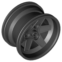
Lego is often cited as the largest tire manufacturer in the world by number of tires. However, there is an upper limit on the size of tire that they make. I came across this post on technicbricks which was talking about using aftermarket tires on a Lego hub. The idea came originally from this thread on eurobricks. As it turns out, you can use a Lego 44772 wheel as the hub for all sorts of other hobby tires that are close in size. The reason you want to do this, and you do want to do this, is that you can put awesome tires on your Lego models. Let me show you a comparison of some of these tires.
"Lego 54120 / Rock Creepers / Rok Lox / Two Face Tires -- From left to right (all mounted on the standard Lego 44772 wheels): Standard Lego 54120 "94.8 x 44R Balloon Tire; RC4WD Rock Creepers 1.9 Scale Tire; RC4WD Rok Lox 1.9 Comp Tire; and RC4WD Two Face 1.9 Offroad Scale Tire. Any 1.9" (48mm Inside Diameter) RC tire in the 37-48mm width range should fit the Lego 44772 wheels." - eurobricks
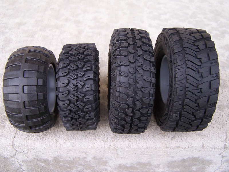 |
| A visual Comparison of tires from the eurobricks thread |
I ordered a total of 8 Two Face tires as they were the largest ones that could be found that still fit the Lego rim. There might be larger ones, but these are the biggest ones that could be found at the moment. The tires are made of significantly softer and gripper rubber than the Lego tires which makes them grip super well. There is some foam inside the tires to keep them ballooned out. Without the foam, the wheels would not support much weight. They fit on the rims very well too. They are not overly tight or too loose; the hub will not rotate inside the tire either. In contrast, the Lego hub will rotate inside the Lego balloon tires if you try hard enough. These tires are simply: beast. I can't wait to throw them on a model!
 |
| The tire fresh out of the packaging. You can see the foam inside the tire. |
 |
| A comparison to the Lego's largest balloon tire and the Two Face tire. |
Thursday, July 19, 2012
Motorola LapDock and Raspberry Pi
I have had two Raspberry Pies for a while now, and I have been wanting to hook them up to a screen, mouse, and keyboard that was space efficient and used fewer chords. I originally had one of the Raspberry Pies setup with a 22inch screen, a full USB keyboard, and a USB mouse. The screen had its own power cable and DVI. In addition, the screen had its own USB hub. To get some usable USB ports, I had to plug another USB cable from the Raspberry Pi to the screen. I then connected the USB Keyboard and mouse to the screen's hub. As you could imagine, there were cords everywhere, and this took a lot of space.
I happen across this tutorial for doing this here. This setup uses a Motorola LapDock that was designed for an Atrix 4G phone. The LapDock is pretty much a screen, keyboard, and mouse in a compact package. When the phone docks with the LapDock, It uses USB and HDMI to control it. As it turns out, you can hook this up the LapDock to other USB devices to use its keyboard and mouse. In addition, you can hook up other devices which use HDMI to drive the screen, and the price of these is falling because the LapDock secretly yesterday's hardware. To get this to work, all you need to do is plug in the USB and HDMI into the Raspberry Pi. That's it. The catch is that you are going to need to get a series of adapters to get this to work. If you want to do this yourself, I would recommend following the tutorial above because it has links to everything you need. To continue this, I need to work on is getting the screen resolution right and 3D printing a case/mount for the Raspberry Pi.
I liked this so much that I decided to get a second LapDock for my server: Moscato. My server lives in my closet because who would be so silly as to actually store coats in there. I have it there so I hear it less. My closet had similar issues with cables for the screen, mouse and keyboard that my Raspberry Pies did. In addition, there is a heat issue having all that jazz working around the clock in a closed space. The LapDock puts out significantly less heat than the previous screen setup did, and it also saves a great deal of space. Check out some pictures of this combination it in action!
 |
| My Raspberry Pi running at Workshop 88 |
 |
| A look at all the setup. |
 |
| A close up of the Raspberry Pi all hooked up. |
 |
| Here is another overall view. |
 |
| A close up of the USB and HDMI connectors of the LapDock |
 |
| A different LapDock hooked up to my server: Moscato. |
 |
| Moscato's old setup. |
Wednesday, July 18, 2012
Arduinos 101 and Workshop 88
 |
| The whole setup |
 |
| Sitting at room temperature. |
 |
| Applying heat from my finger. |
 |
| Applying a cold water bottle to the temperature sensor. |
Subscribe to:
Comments (Atom)