I have had some major issues with this blog since they updated to the new interface. Somehow, my blog got stuck without the ability to change settings, layouts, templates etc. I have not been able to find a solution to the problem. To fix this. I am going to continue my blogging at phoenix.initiate(); It is cleaner, sleeker, easier to read, and I have all of the settings! Don't worry, I transferred all the posts from Man and Machine to phoenix.initiate();
Thursday, July 26, 2012
Super Sumo for NXT and NXShield Robots
 |
| A stylized sumo wrestler from here |
The first thing that I think a super sumo category would have is a higher weight limit. Let's kick it up to 4.4 pounds (2kg). The increased weight will allow for more diversity for exotic drive trains and weapons. Right now, most sumo bots end up limited to 1 motor per wheel or 3 for the drive train in total if you use a differential like what I did here. There isn't a lot of weight available to make actuated plows, lifts, hammers, or whackers. Why not kick it up a notch? Raising the maximum weight would also help to allow room for the NXT to control other Lego systems such as Power Functions. In addition, a second NXT with up to 3 extra motors (totaling 6 motors) would also fit within the weight limit of 4.4 pounds since 1 NXT and 3 motors can fit within the weight limit of 2.2 pounds. How cool would that be?
But why make this a Lego purist affair? The NXT was designed to be an open platform for people to develop for. Places like Becreo, Mindsensors, HiTechnic, Dexter Industries have spent considerable amounts of energy building things for the NXT platform. Given a greater weight and size limit, more interesting accessories can be used. To accommodate both the purists and non, I would imagine that there would be a limited and unlimited category. The limited category would strictly be official Lego parts only. The unlimited category would be significantly more open. The caveat would be that the unlimited category would enforce that you would have to use an NXT or an NXshield. However, other than the controller, hobby servos, metal parts, 3D Printed parts, and home brewed sensors would all become acceptable things to use in your unlimited class super sumo robot. If you are looking to build your own dimensionally compatible parts, you can see a website here that has all the measurements you need.
One other important factor would be the sumo ring itself. I built one that is for regular sumo. Not to break any compatibility with the previous generation ring, I would imagine a four foot diameter circular and flat field would become the minimum size. I would then also suggest that the maximum size should go up to 6 feet in diameter. Moreover, there would be a 2 inch wide white stripe around the circumference of the field regardless of diameter.
Here is a brief summary
Super Sumo Specifications:
Common
4.4 pound maximum weight
1.5 foot square maximum footprint
4 foot to 6 foot sumo ring with a white 2 inch wide circumference.
no enforced maximum number of motors, sensors, or Lego elements.
no limitations limiting the nature of the software platform
Limited Category
Official Lego parts only
Unlimited Category
Must use an NXT or NXShield to control the robot
Non-Lego parts allowed ;)
Arduino 201 and Workshop 88

A few weeks ago, I started programming Arduino microcontrollers at Workshop 88 for the first time in the Arduino 101 class. Today was the second class: 201. As it turns out, I completely forgot to bring any Lego motors with me to demonstrate if things were working with the NXShield. Shame on me. However, I did have a continuous rotation servo that I hooked into the servo pin headers. We were able to use the native functionality of the Arduino's servo libraries to control the servo. This will allow robots to use both Lego Motors and Hobby Servos in their robots with the NXShield. We first started tinkering by playing around with the built in LED which flashes red, blue and green in the NXShield. After that, we decided to try getting the servo to work.
The project actually works! The Arduino received and transmitted information to the terminal prompt on my screen. If you entered "f" for forward, the speed increased. If you entered "b" for backwards, the speed decreased. You could even get the motor rotating in both directions. If you entered anything but "f" or "b", then the motor would come to a hard stop. You You can see the code used in the video here.
 |
| We have intended motor movement! |
 |
| Computer Science! |
 |
| Blinking LED Test |
 |
| Blinking LED Test |
 |
| Showing the Setup |
 |
| Here is a closeup of the NXShield, Arduino, and Motor. |
Monday, July 23, 2012
4 Wheel Drive Truck Design Considerations and Two Face Tires
I bought eight Two Face tires to try out on my own four wheel drive off road truck. Here are some pictures of the truck before and after. You also might notice the shiny Technic style frame that you don't recognize. Those are 37 unit long 303 stainless steel beams from Becreo. They are extremely strong and made building the model really easy. There is no frame flex which helps the suspension actuate properly which is awesome to watch. You also might notice a PSP-Nx-v4 from Mindsensors. This model uses an NXT to power the Power Functions motors with a series of adapters like these and those. The NXT receives information from the PSP-x-v4 in a sensor port to control the model. For the programming part, I pretty much mapped one of the Playstation 2 controller thumb-sticks to speed and the other to steering with some scaling values. It was that simple.
The front and rear module are primarily constructed of Technic frames. This makes the construction of the module itself extremely strong. The strong modules in combination with the Becreo frame make the structure effectively invincible. with the Above and below you can see the differential which is powered by two Power Function XL motors. This gives the truck plenty of torque. However, the XL motors snap the differential gears like they are made butter. I have had to replace the differential gears at least 10 times in the four weeks of teaching at InZone because they are so easy to break with that much power going into them. Cursed ABS plastic! I might have to make some metal ones....The other weak point are the Lego suspension parts used to get 4 wheel independent suspension. The suspension parts rely on very small nubs to transfer torque at varying angles. After seeing the differential gears break, I am pretty much waiting to break the half shafts going into the wheels if I keep this model on XL motors. Here is a motor of the truck working and breaking a gear. It's really hard to drive the truck and hold the camera. Sorry for a bit of a dark picture.
The simple way to solve this issue is to put less power into the differential. I originally had Power Functions Medium motors powering the modules, but I put XL motors in the model to increase its off road performance. I had fewer issues breaking parts with the medium motors; I might go back to that configuration to solve that problem. One way to solve the differential issue would be to significantly gear up the motors before they arrive at the differential. This would allow the differential to run at high speed but with low torque. The problem would be that the half shafts coming out of the differential would need to be geared down again...significantly. Having all of those gears would be become extremely inefficient due to friction which would rob all of the advantages of putting more power into the system in the first place. Therefore, putting some Medium motors instead of the XL motors would be simpler. The bottom line is that most of these parts were never meant to handle that much abuse. If you look at Lego's current Technic models, most of them are motorized by one or maybe two motors at most to provide demonstrations multiple functions; they are meant to show off clever mechanics instead of some silly 23 year old trying to do silly things. I broke this when I took the video. You might notice that this is much less of gear.

The next, and more involved idea, would be to change the differential to a spool which is a straight axle connecting the two sides. While this would fix the issue with the differential gears cracking apart, there would be a lot of stress on the half shaft couplings since the wheels cannot turn at the proper speeds. How do you fix that? You ditch the independent 4 wheel suspension in favor of a live axle setup. You might notice that in real life, pretty much all of the serious off road vehicles have dependent live axle setups. This would be similar to something like a Jeep Wrangler suspension. They have that for a reason: durability and simplicity. In my next post, I will talk about building a proper crawler!
You can see some of the Technic Frames here in the construction. It is actually pretty simple. You can also see the arms that stabilize the double wishbone suspension.
The new tires are pretty cool. They add a lot of ride height to the model. They also make the model go pretty fast since their radii are significantly greater!
 |
| An Overall View |
 |
| Front Module |
The simple way to solve this issue is to put less power into the differential. I originally had Power Functions Medium motors powering the modules, but I put XL motors in the model to increase its off road performance. I had fewer issues breaking parts with the medium motors; I might go back to that configuration to solve that problem. One way to solve the differential issue would be to significantly gear up the motors before they arrive at the differential. This would allow the differential to run at high speed but with low torque. The problem would be that the half shafts coming out of the differential would need to be geared down again...significantly. Having all of those gears would be become extremely inefficient due to friction which would rob all of the advantages of putting more power into the system in the first place. Therefore, putting some Medium motors instead of the XL motors would be simpler. The bottom line is that most of these parts were never meant to handle that much abuse. If you look at Lego's current Technic models, most of them are motorized by one or maybe two motors at most to provide demonstrations multiple functions; they are meant to show off clever mechanics instead of some silly 23 year old trying to do silly things. I broke this when I took the video. You might notice that this is much less of gear.

The next, and more involved idea, would be to change the differential to a spool which is a straight axle connecting the two sides. While this would fix the issue with the differential gears cracking apart, there would be a lot of stress on the half shaft couplings since the wheels cannot turn at the proper speeds. How do you fix that? You ditch the independent 4 wheel suspension in favor of a live axle setup. You might notice that in real life, pretty much all of the serious off road vehicles have dependent live axle setups. This would be similar to something like a Jeep Wrangler suspension. They have that for a reason: durability and simplicity. In my next post, I will talk about building a proper crawler!
 |
| Rear Module |
 |
| Rear Suspension Geometry |
 |
| Getting some new tires! |
 |
| New and Old tires |
 |
| Outfitted with New Tires |
Lego Hubs with Non-Lego Tires
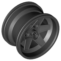
Lego is often cited as the largest tire manufacturer in the world by number of tires. However, there is an upper limit on the size of tire that they make. I came across this post on technicbricks which was talking about using aftermarket tires on a Lego hub. The idea came originally from this thread on eurobricks. As it turns out, you can use a Lego 44772 wheel as the hub for all sorts of other hobby tires that are close in size. The reason you want to do this, and you do want to do this, is that you can put awesome tires on your Lego models. Let me show you a comparison of some of these tires.
"Lego 54120 / Rock Creepers / Rok Lox / Two Face Tires -- From left to right (all mounted on the standard Lego 44772 wheels): Standard Lego 54120 "94.8 x 44R Balloon Tire; RC4WD Rock Creepers 1.9 Scale Tire; RC4WD Rok Lox 1.9 Comp Tire; and RC4WD Two Face 1.9 Offroad Scale Tire. Any 1.9" (48mm Inside Diameter) RC tire in the 37-48mm width range should fit the Lego 44772 wheels." - eurobricks
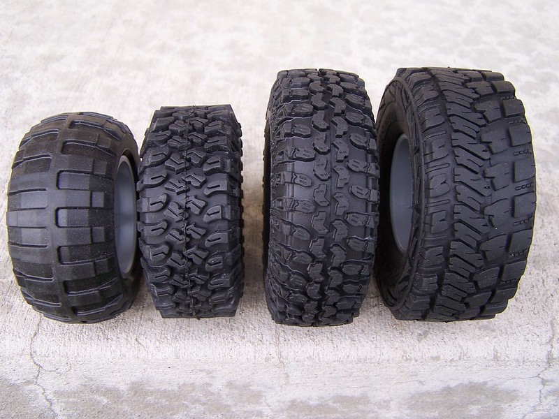 |
| A visual Comparison of tires from the eurobricks thread |
I ordered a total of 8 Two Face tires as they were the largest ones that could be found that still fit the Lego rim. There might be larger ones, but these are the biggest ones that could be found at the moment. The tires are made of significantly softer and gripper rubber than the Lego tires which makes them grip super well. There is some foam inside the tires to keep them ballooned out. Without the foam, the wheels would not support much weight. They fit on the rims very well too. They are not overly tight or too loose; the hub will not rotate inside the tire either. In contrast, the Lego hub will rotate inside the Lego balloon tires if you try hard enough. These tires are simply: beast. I can't wait to throw them on a model!
 |
| The tire fresh out of the packaging. You can see the foam inside the tire. |
 |
| A comparison to the Lego's largest balloon tire and the Two Face tire. |
Thursday, July 19, 2012
Motorola LapDock and Raspberry Pi
I have had two Raspberry Pies for a while now, and I have been wanting to hook them up to a screen, mouse, and keyboard that was space efficient and used fewer chords. I originally had one of the Raspberry Pies setup with a 22inch screen, a full USB keyboard, and a USB mouse. The screen had its own power cable and DVI. In addition, the screen had its own USB hub. To get some usable USB ports, I had to plug another USB cable from the Raspberry Pi to the screen. I then connected the USB Keyboard and mouse to the screen's hub. As you could imagine, there were cords everywhere, and this took a lot of space.
I happen across this tutorial for doing this here. This setup uses a Motorola LapDock that was designed for an Atrix 4G phone. The LapDock is pretty much a screen, keyboard, and mouse in a compact package. When the phone docks with the LapDock, It uses USB and HDMI to control it. As it turns out, you can hook this up the LapDock to other USB devices to use its keyboard and mouse. In addition, you can hook up other devices which use HDMI to drive the screen, and the price of these is falling because the LapDock secretly yesterday's hardware. To get this to work, all you need to do is plug in the USB and HDMI into the Raspberry Pi. That's it. The catch is that you are going to need to get a series of adapters to get this to work. If you want to do this yourself, I would recommend following the tutorial above because it has links to everything you need. To continue this, I need to work on is getting the screen resolution right and 3D printing a case/mount for the Raspberry Pi.
I liked this so much that I decided to get a second LapDock for my server: Moscato. My server lives in my closet because who would be so silly as to actually store coats in there. I have it there so I hear it less. My closet had similar issues with cables for the screen, mouse and keyboard that my Raspberry Pies did. In addition, there is a heat issue having all that jazz working around the clock in a closed space. The LapDock puts out significantly less heat than the previous screen setup did, and it also saves a great deal of space. Check out some pictures of this combination it in action!
 |
| My Raspberry Pi running at Workshop 88 |
 |
| A look at all the setup. |
 |
| A close up of the Raspberry Pi all hooked up. |
 |
| Here is another overall view. |
 |
| A close up of the USB and HDMI connectors of the LapDock |
 |
| A different LapDock hooked up to my server: Moscato. |
 |
| Moscato's old setup. |
Wednesday, July 18, 2012
Arduinos 101 and Workshop 88
 |
| The whole setup |
 |
| Sitting at room temperature. |
 |
| Applying heat from my finger. |
 |
| Applying a cold water bottle to the temperature sensor. |
Monday, July 16, 2012
Combining a Nitro Motor or High Powered Motors with Mindstorms and a 8070 Super Car
I have always wanted to make a Technic super car. I have gotten close in my own way, but I never fully built anything that truly satisfied me. In my mind, I have always wanted a Lego Super car that could travel at or near highway speeds. As it turns out, ganging Lego motors can only go so far.
The other option would be use an actual nitro motor. This is an example of a nitro motor that I would consider. I would totally be cool with this if it doesn't melt anything and I can find one small enough to fit in the car. It looks like the really cheap ones are 50 bucks a pop. I would be totally new to this side of the hobby. This would be mixing the geeky Technic side with the shiny semi custom RC car side. This really should happen sooner rather than later. I would have the NXT control a motor which actuated the throttle. I think the nitro motors like these have a centrifugal clutch which would be perfect for this application. It will let the user slowly apply torque to the drive train without snapping the parts. In addition, it will also let the car idle and not creep. I did design a heavy duty differential in CAD that I am going to 3D print eventually. It uses 4 knob wheel gears since they are the strongest type of gear Lego has. It also has bearings to help everything run smoothly. One day I might have a nitro motor abusing one of my heavy duty custom differentials :)
You might be curious how I am actually going to connect any of this to the Lego system itself. I am getting a 3D printer, and I am going to print the parts I need to get either the electric motor or nitro engine mounted into the car. I also have a small hobby lathe, drill press, and mini CNC mill to help me accomplish this project. Lets hope the propulsion system doesn't melt whatever it touches. If it does, this might end up being the first liquid cooled nitro Lego car.
The platform that I am thinking about modifying is an 8070 super car. My mom gave it to me for my 23rd birthday. Thanks mom! It has some pretty nifty features that I would like to preserve. It has "lambo doors", a pop open hood, a pop open rear spoiler, steering, and propulsion. It also has one of Lego's moving decorative engines under the hood, but I don't really find that overly amusing. It is going to get replaced by an actual engine of some sort. In the stock setup, all of the functions are actuated by a medium motor mated to a Lego transmission, and moving the stick around in the drivers area changes what function the medium motor actuates. I was studying the directions last night to see how easy it would be to change everything. Lego did a great job integrating everything together which will make this a bit of a pain to modify. The transmission is the centerpiece of the model; it is where the magic happens to make all the functions work. I would remove the transmission, and try to motorize the functions individually so that the NXT can control the functions. It looks like most of the functions operate with a worm-gear type setup which moves a crank and then a set of linkages. It might be possible to replace the crank and linkage setups with some Lego pneumatics. There are some minor features that I want to add too. One thing that super cars ought to have are working headlights, and I will add some remote control functionality with a Mindsensors PSP-Nx-4c. That will give me a slick user interface and lots of buttons to control the other functions of the car.
In summary, this is really going to take the term "super car" to the next level. An actual source of torque such as a hobby aircraft motor or nitro engine paired with the intelligence of an NXT will make an extremely fast, one of a kind, and programmable machine.
 |
| A Hobby Aircraft Motor |
In contrast, a hobby electric aircraft motor would do very well as the main driving motor to propel the car at warp speed. I want to get one that puts out around a horsepower or more. If I used this solution, It will be controlled by a Mindsensors NXT Relay Driver. Moreover, the NXT will control the NXT Relay Driver which will control another relay for high power use that connects the motor to the battery. This solution would be simple and avoid the need to use a proper motor controller, however, the sudden torque might snap the Lego pieces. It might be necessarily to get a high current motor controller to try to smooth out the sudden onset of torque.
| A Nitro Motor |
You might be curious how I am actually going to connect any of this to the Lego system itself. I am getting a 3D printer, and I am going to print the parts I need to get either the electric motor or nitro engine mounted into the car. I also have a small hobby lathe, drill press, and mini CNC mill to help me accomplish this project. Lets hope the propulsion system doesn't melt whatever it touches. If it does, this might end up being the first liquid cooled nitro Lego car.
 |
| Lego's 8070 Super Car |
The platform that I am thinking about modifying is an 8070 super car. My mom gave it to me for my 23rd birthday. Thanks mom! It has some pretty nifty features that I would like to preserve. It has "lambo doors", a pop open hood, a pop open rear spoiler, steering, and propulsion. It also has one of Lego's moving decorative engines under the hood, but I don't really find that overly amusing. It is going to get replaced by an actual engine of some sort. In the stock setup, all of the functions are actuated by a medium motor mated to a Lego transmission, and moving the stick around in the drivers area changes what function the medium motor actuates. I was studying the directions last night to see how easy it would be to change everything. Lego did a great job integrating everything together which will make this a bit of a pain to modify. The transmission is the centerpiece of the model; it is where the magic happens to make all the functions work. I would remove the transmission, and try to motorize the functions individually so that the NXT can control the functions. It looks like most of the functions operate with a worm-gear type setup which moves a crank and then a set of linkages. It might be possible to replace the crank and linkage setups with some Lego pneumatics. There are some minor features that I want to add too. One thing that super cars ought to have are working headlights, and I will add some remote control functionality with a Mindsensors PSP-Nx-4c. That will give me a slick user interface and lots of buttons to control the other functions of the car.
In summary, this is really going to take the term "super car" to the next level. An actual source of torque such as a hobby aircraft motor or nitro engine paired with the intelligence of an NXT will make an extremely fast, one of a kind, and programmable machine.
Sunday, July 15, 2012
Motorizing a Lego 8081-B Model Hot Rod
I want to get into motorizing some of Lego's Technic cars. One present that I got for my 23 birthday was an 8081 set from Jessica. This set can build two specified models. The A model is a truck. The B model is a hot rod. I decided to build the hot rod because I can't bear the thought of a just two wheel drive truck. However, a two wheel drive hot rod seems perfectly natural. After building the stock hot rod, I wanted more. I then set out motorizing this model to warm up for combining Mindstorms with an 8070 model supercar that I also got for my birthday. Thanks Mom!
One of the first things that I did was changing the wheels. I substituted the balloon style tires for the street style tires. I also made the rear wheels larger to give more of a hot rod look. I wanted to maintain the stock functions as much as possible. This meant keeping the working model engine block, dimensions, and body. I pretty much resided myself to taking the driver's area apart to cram in the necessarily parts. I removed the seats, and placed a Power Functions battery box in the driver's area. I wasn't quite able to get the geometry compact enough to get the battery box fully inside the area. This meant that I had to remove the roof.
I then used the existing steering system including the front steering assemblies and the shaft which is used to move the steering by hand. I added a Power Functions medium motor with a worm-gear assembly that uses the white 24 tooth slip gear to actuate the steering. This not only allows for the steering to be precise and controllable, but also lets the motor try overrun the steering boundaries without causing any damage. This is important because kids do not seem to observe common sense with playing with other people's stuff.
While I was at it, I also put the Power Functions IR Receiver in the rear of the model. It fits quite nicely back there and helps the steering motor stay snug against the frame. I had to do a little bit of mechanical acrobatics to actually connect the receiver to the vehicle because the Technic holes ended up being spaced half off.
Given that I want to preserve the engine block reciprocation, I had to also preserve the shaft that connected the crankshaft to the wheels. Other than redesigning huge chunks of the model, preserving the shaft was the only real option. I searched for ways to finagle motors in at right angles, but nothing was quite fitting as well as I really wanted. Finally, I saw the KISS solution which was mounting another medium motor directly to the back of the frame which held the differential. It was much easier than doing any other solution and also preserved the frame and body. I am pretty happy with how this turned out:
 |
| Overall View |
 |
| Right Side View |
 |
| Left Side View |
 |
| Underside View |
Friday, July 13, 2012
Three Motor Sumo Robot
 |
| An LDD Screenshot of the robot |
This is a video from a Mindstorms class that I taught at InZone
This is a video from a Mindstorms class that I taught at InZone
I wanted to share my sumo robot with you. My sumo robot is pretty cool. In the scheme of things, there are better sumo robots, however, mine has proven to be decent and fun to work with. One of the things that makes my robot special is that it uses all three of the NXT motors for movement. This is accomplished with the third motor powering a differential which aides the other two motors. The other two motors each power a wheel directly. I have a Lego Digital Designer file so you can see it and build your own. The nifty part are the geometries that I used to make the three motor core solid. With lithium batteries, mine weighs in at 2.16 pounds which is right below the 2.2 maximum. You can get all the files for the robot here. The files include the Mindsensors firmware, NXT-G program, additional software blocks, and a Lego Digital Designer file. If I were to build another robot, I would change the pusher design so that there was a angled edge running on the ground. The Lego Technic beams have rounded edges which do not really make a good wedge to get under an opponent.
I programmed it in NXT-G. The program is a finite state machine. There are three parts of the program running at the same time. One part gets the values from the sensors, one part checks the state and then executes the state, and the other part is the logic which sets the state. The robot has the following states: forward, backward, turn left, turn right, or stop. Based on the sensor values coming in, the state is set and then executed. I am using the Mindsensors firmware which helps to make the operation smoother when compared to the stock firmware. I am also using the "mini blocks" which seem to be a bit better.
There are three programs for this robot. The first one is called JAYSUMOFINAL. It is a full sumo program meant to conform to the rules of official Lego sumo competitions. It has the 5 second countdown after the start and can choose the the initial turn direction. JAYSUMOEXPRESS is similar to the previous program except it does not have a countdown and the user doesn't choose the initial turning direction. The last program is called JAYSUMOPSPNX-4. It is meant to be use with a Mindsensors PSP-Nx-v4 for remote control. To use this program, one simply unplugs the rear light sensor and plugs in the receiver. The receiver is easily mounted sideways in front of the NXT. This gives the user a slick and responsive interface for remote control operation.
Monday, July 9, 2012
Shapeoko Mill
I have been looking forward to building this Shapeoko Mill for a while now. I want to own my own basic manufacturing equipment so that I can start to build prototypes of my ideas. The Shapeoko is a really good design and it is easy to build upon. Right now, I am working on getting a simple job competed as an example. I also have a Solidoodle 3D printer in the mail right now. I am very pleased with how well it turned out. The designers really went out of their way to make sure that you could build this mill quickly and without additional tools that did not come with the kit. I spent a Friday night and part of a Saturday building my mill. Total build time might have been around 5 to 7 hours. One part of the mill that I thought could use some improvement was the way the rubber gear belts were connected to the frame. The belts are important because the X/Y gantries traverse their working envelope by creeping along the belts. The points where the belts are meant to fasten do not provide as sturdy of a connection that I would like and are out of proper alignment. I changed how the belts were fastened to improve the alignment of the belts and their connection to the frame. Once my 3D printer comes in, I will devise some sort of clever way to fasten the belts to the frame in a more permanent and streamlined fashion.


 |
| beginning the plates |

 |
| some of the tools and connectors |
 |
| Would you look at that, it is looking like something! |

 |
| My desk was really awesome. |
 |
| The mechanicals are complete. |
 |
| Finished the electronics! |
 |
| Fin |
Wednesday, July 4, 2012
Lego Robotics Sumo Ring
I have been wanting to build a sumo ring for battling hobby robots. Today was the day. I intend on using it to test my own bots as well as a teaching tool and to help out at events at Brickworld. I teach Lego Mindstorms robotics at Harper College through a program called Inzone. The ring is made from a piece of 4ft by 8ft by 1/2in plywood. My dad and I bought it and had it cut in half at Home Depot. Both sides of the plywood were used to form a 4ft by 4ft by 1in thick square. After some geometry to find find centers, we did some jig-sawing to make it a circle. The two rounds are secured to each other by some gorilla glue and 5 screws. The screws come up from the bottom so keep the battle surface free of any imperfections. We did some painting and even made a mask for the white stripe around the outside. If I were to do it again, I would 3D print a tool with my Solidoodle that would basically be a swing arm that attached to a jigsaw. This would ensure that the radii swept by the saw is exactly constant throughout the duration of the arc. In addition, I would also add a mount to attach a razor blade so that the masking and painting process became faster and more exact. That being said, we put a day into building this thing, and it turned out really well!
 |
| Cutting |
 |
| Sanding |
 |
| Gluing the two halves together |
 |
| Black Paint |
 |
| Masking for White Border |
 |
| Done! |
Subscribe to:
Posts (Atom)